
Nanomaterial Scientific Illustration

15 archived cases

Compare the visible organization of research objects, processes, interfaces and local views. Each detail page retains its original artwork and associated paper record.

Discuss a paper figure
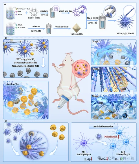
Piezoelectric Nano-Urchins for Drug-Resistant Biofilm Infections

Piezoelectric Nano-Urchins for Drug-Resistant Biofilm Infections

Material preparation runs horizontally across the top. An animal application connects to the central scene, with functional regions on the left and stage panels on the right. Read preparation and application location before the local stages and lower results.

Biomedical researchScientific paper figurePublished work
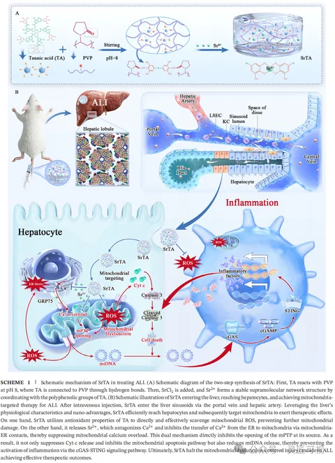
Mitochondria-Targeted Tannic Acid–Strontium Nanomedicine

Mitochondria-Targeted Tannic Acid–Strontium Nanomedicine

Material preparation sits above an animal-to-liver view. Tissue details lead into cellular and organelle panels below. Insets and arrows separate the material, application location and intracellular relationships across scales.

Biomedical researchScientific paper figurePublished work
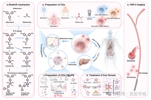
NIR-II Carbon Dots for Hepatobiliary Theranostics

NIR-II Carbon Dots for Hepatobiliary Theranostics

Lettered panels separate carbon-dot preparation, structural mechanisms and an imaging scene. A central object connects applications, while functionalization and local application information continue along the bottom.

Biomedical researchScientific paper figurePublished work
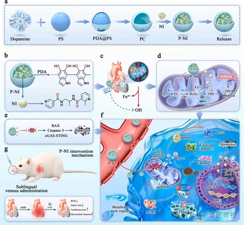
ROS-Scavenging Nanocarriers and Myocardial Injury

ROS-Scavenging Nanocarriers and Myocardial Injury

Sequential steps across the top show nanocarrier preparation. Lettered regions connect the material structure, heart location and intracellular information. A larger cellular inset holds the dense relationships, with smaller panels for administration and results.

Biomedical researchScientific paper figurePublished work
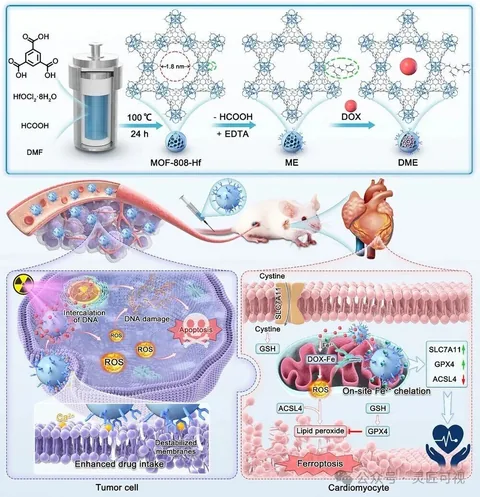
EDTA-Functionalized MOFs for Tumor Therapy and Cardiac Protection

EDTA-Functionalized MOFs for Tumor Therapy and Cardiac Protection

MOF structural changes occupy the top. The middle links animal, tissue and heart views, followed by two cellular environments side by side below. Background colors and outlines distinguish each region.

Biomedical researchScientific paper figurePublished work
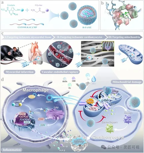
Heart-Targeted Nanomedicine and Mitochondrial Damage

Heart-Targeted Nanomedicine and Mitochondrial Damage

Assembly and structural details appear above a sequence linking the heart, cells and mitochondria. Two cellular environments follow below. Stage bars, insets and arrows establish an overview-to-detail path.

Biomedical researchScientific paper figurePublished work
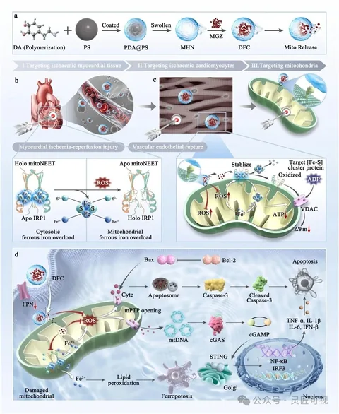
mitoNEET-Related Nanotherapeutics for Myocardial Injury

mitoNEET-Related Nanotherapeutics for Myocardial Injury

The top sequence establishes carrier assembly before stage bars and insets lead to cells and mitochondria. A protein-structure comparison and a larger cellular mechanism panel hold separate details, coordinated by legends, arrows and numbering.

Biomedical researchScientific paper figurePublished work
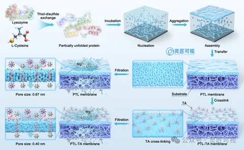
Amyloid-Like Assembly of Protein Nanofiltration Membranes

Amyloid-Like Assembly of Protein Nanofiltration Membranes

Protein structures at the top lead through nucleation and assembly, then transfer and crosslinking to membranes below. Paired membrane surfaces and pore details distinguish process order from structural comparison.

Materials chemistryScientific paper figurePublished work
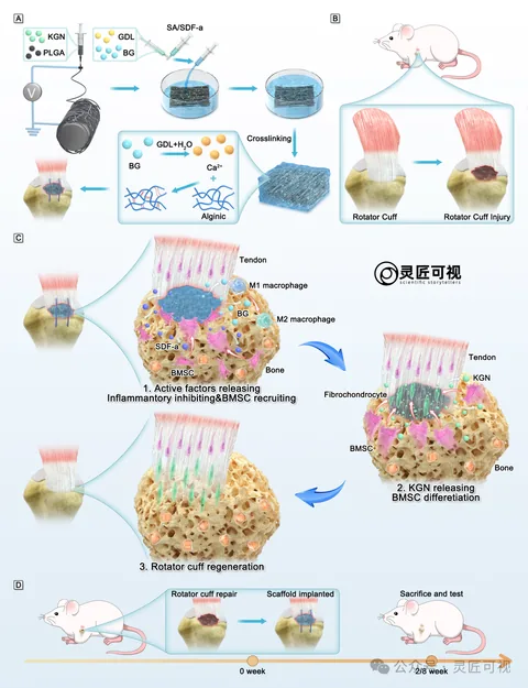
Hydrogel–Nanofiber Scaffolds for Rotator Cuff Repair

Hydrogel–Nanofiber Scaffolds for Rotator Cuff Repair

Separate preparations for a fibrous membrane and hydrogel lead to the rotator-cuff injury location. Three local stages organize tissue changes, while a lower timeline records implantation and observation arrangements.

Biomedical researchScientific paper figurePublished work
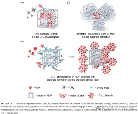
Water Clustering in ZIF-8 and Methane Storage

Water Clustering in ZIF-8 and Methane Storage

Two upper panels distinguish internal pores from interparticle spaces. A larger lower panel connects facet changes. Water, methane, sites and cage structures share a legend at the bottom.

Energy and functional materialsScientific paper figurePublished work
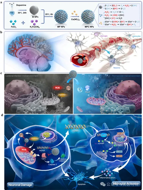
Sequentially Targeted Nanomedicine and the Neural Microenvironment

Sequentially Targeted Nanomedicine and the Neural Microenvironment

A top preparation workflow leads to brain and vessel locations. Two local environments are compared in the middle. Larger neuron and microglial panels below hold the molecular pathways.

Biomedical researchScientific paper figurePublished work
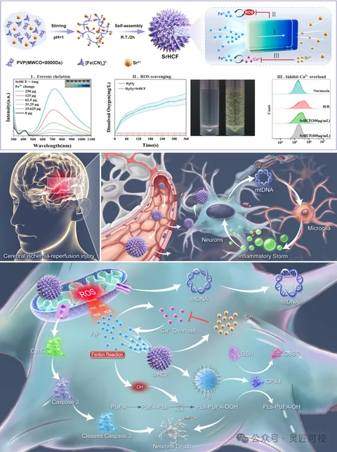
Strontium-Substituted Nanomedicine for Cerebral Injury

Strontium-Substituted Nanomedicine for Cerebral Injury

Particle assembly and characterization sit at the top. Brain injury, vessel and neuron views lead to a large lower cellular panel. Curves, apparatus and mechanism arrows occupy separate regions.

Biomedical researchScientific paper figurePublished work
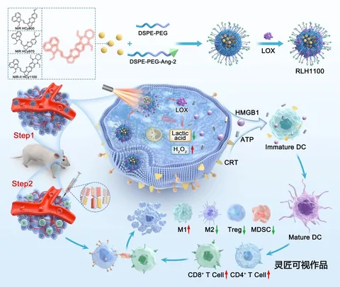
Hemicyanine Nanoparticles and Glioblastoma Photoimmunotherapy

Hemicyanine Nanoparticles and Glioblastoma Photoimmunotherapy

An upper assembly sequence connects to two labeled delivery stages and a vessel. A larger cell on the right holds the main relationships; different immune-cell forms and arrows continue below.

Biomedical researchScientific paper figurePublished work
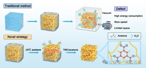
Ice-Dissolving Crosslinking of Polyelectrolyte Monoliths

Ice-Dissolving Crosslinking of Polyelectrolyte Monoliths

Two rows begin with similarly viewed porous blocks. The upper route connects a vacuum setup and annotation box; the lower route shows solvent treatment and crosslinking. A right-hand inset links macropores to polymer chains and junctions.

Materials chemistryScientific paper figurePublished work
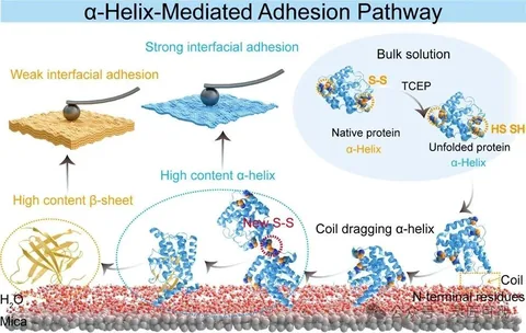
α-Helix-Mediated Protein Adhesion

α-Helix-Mediated Protein Adhesion

The first illustration connects protein structural changes to an interface and compares two adhesion states. The second places surface structures, protein insets and plotted results together, using yellow and blue to link corresponding information.

Materials chemistryScientific paper figurePublished work