
How to Draw a Catalytic Reaction Mechanism
Separate the catalyst structure, reaction pathway and supporting evidence. Define active sites and arrow meanings before using perspective or enlargement to explain the interface.
Choose the figure’s scientific level
A catalyst-preparation workflow, a surface-reaction schematic and an energy diagram answer different questions. Record the material state, reactants, intermediates and products that are actually supported. Do not add an atomic site or mechanistic step merely to fill a 3D scene.
Establish the support and selected sites
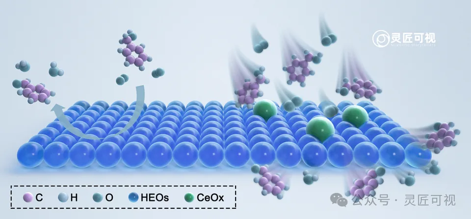
The cerium-doped high-entropy oxide archive uses a continuous blue surface, a smaller number of green sites and molecules above. The color key identifies the objects; the associated paper supplies the scientific context. Geometry and color alone cannot prove which site is active.
Give arrows one defined role
Distinguish molecular approach, a proposed surface process and departure. A preparation arrow may indicate sequence without asserting a reaction mechanism. If measurements or calculations support a step, retain the relevant evidence and caption context rather than treating a visual arrow as proof.
Keep apparatus and microscopic explanation separate
The fixed-bed reactor illustration assigns numbers to equipment and uses a separate circular detail for microscopic structure. A reader can inspect flow and local structure without assuming that they occupy the same physical scale.
Review before export
Verify atom and species names, arrow direction, legend, site identity, source permissions and final-size labels. Keep structural source files with any rendered view. Continue with materials chemistry, 3D-LAB preparation or mechanism design services.
Sources and scope
Sources apply within their stated scope. Archive records describe existing work; international account access and checkout remain closed.
Choose the next step
Understand the platform · Scope a design commission · Contact support